
Hi,
Rather - puzzling. The code that you posted as "bad code" looks fine to me.
Where you noted that there is no G01, there does not have to be one... G01 is modal, once a G01 is executed,the mode stays G01 until changed.
Thus the feed rate movement mode is set by the line that says
G01 Z0.2500 F11.0
two lines before the
M6 T2 line
will set the mode to G01 and it will still be G01 after the M6 line.
Neither the M6 nor the M03 lines will change the feed mode - so it should be G01 when you get to the line that says
M03 S2800 Notice no G01 here
Just to be sure, I took that code and fired up mach+MSM on my desktop machine just before I wrote this response (mach configured for a pp, just no cable on the PP to go to any CNC electronics).
Note that You can see the G1 mode in the mode status line at the bottom of the run page in MSM.
I ran the code in single block mode and watched the G1 state at each line.
it goes to g01 before the M6 and stays that way. The only time the status line is not G01 is during the G73 canned cycle - then the G1 disappears from the status line (as we are in the canned cycle). it comes back at the G01 after the G80 that cancels the G73 canned cycle.
I'd suggest that you try this with the smooth stepper - single block thru the code and see what mach says the mode is are each line of the program. It works fine for me on the PP, it it does something different for you on the SS, I'd start considering a SS bug - but I admit that that possibility seems pretty low to me.
In any case, I think both code versions are valid gcode and I'm not seeing g01 being run as g00 moves.
Dave
Guage line measurement and TLO Touchplate measurement.
Re: Guage line measurement and TLO Touchplate measurement.
Productivity Software for Personal CNC Machinists
http://www.CalypsoVentures.com
http://www.CalypsoVentures.com
Re: Guage line measurement and TLO Touchplate measurement.
I can only go by what that machine did when running the code as in the first example. I'm on a PP as well so it's not a Smooth Stepper issue.
I understand that in the first example the control is placed in G01 for retract of the Z after the drill cycle and that code is technically valid however that end result was the full rapid movement of the machine. Obviously the MACH3 handling of the G-Code isn't an MSM problem. I'm just trying to pin point it as either a Mach 3 bug, A RhinoCam issue or some combination of the 2 so that I can avoid it in the future.
I understand that in the first example the control is placed in G01 for retract of the Z after the drill cycle and that code is technically valid however that end result was the full rapid movement of the machine. Obviously the MACH3 handling of the G-Code isn't an MSM problem. I'm just trying to pin point it as either a Mach 3 bug, A RhinoCam issue or some combination of the 2 so that I can avoid it in the future.
Re: Guage line measurement and TLO Touchplate measurement.
Hum,
I'm concerned since the G01->G00 seems to happen across a M6 sequence.
An M6 is not supposed to change the motion mode, but it's also true that an M6 is a funny animal in mach. It's a gcode where mach makes calls to user scripts (M6start and M6end) to implement the M6 actions. This is the hook that MSM uses to implement all the MSM tool change features. The MSM code goes to great lengths to make sure that the mach state on exit from the M6 stuff is the same as when it was entered.
But, I suppose that it's possible that there could be a bug that causes the G01 state to get changed.... but that's the type of thing that gets noticed really quickly and causes lots of people to holler... so I'm left being unsure about things.
I can think of two tests that would be interesting:
1) Could you run the same test case using teh stock 1024 screen set?
IF you do NOT see the rapid move with 1024, then I"ll get really worried as this test would primarily remove the MSM M6 code from the scenario.
2) I could go run your test code on my main mill. The testing I've done so far is on the desktop machine and while the feed rates all show correctly on the screen, I suppose that the screen could be seeing one thing while the movement is actually something else. Unfortunately, I can't do that test right away as I have a project set up on the mill that will be painful to tear down and redo today.
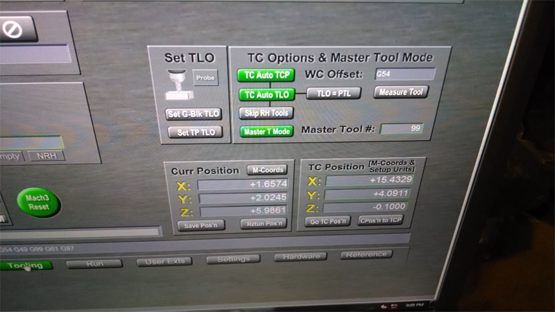
Could you take a screen shot of the MSM tooling page for me? I'd like to know exactly what tool change options you are invoking when the test code is run.
Dave
I'm concerned since the G01->G00 seems to happen across a M6 sequence.
An M6 is not supposed to change the motion mode, but it's also true that an M6 is a funny animal in mach. It's a gcode where mach makes calls to user scripts (M6start and M6end) to implement the M6 actions. This is the hook that MSM uses to implement all the MSM tool change features. The MSM code goes to great lengths to make sure that the mach state on exit from the M6 stuff is the same as when it was entered.
But, I suppose that it's possible that there could be a bug that causes the G01 state to get changed.... but that's the type of thing that gets noticed really quickly and causes lots of people to holler... so I'm left being unsure about things.
I can think of two tests that would be interesting:
1) Could you run the same test case using teh stock 1024 screen set?
IF you do NOT see the rapid move with 1024, then I"ll get really worried as this test would primarily remove the MSM M6 code from the scenario.
2) I could go run your test code on my main mill. The testing I've done so far is on the desktop machine and while the feed rates all show correctly on the screen, I suppose that the screen could be seeing one thing while the movement is actually something else. Unfortunately, I can't do that test right away as I have a project set up on the mill that will be painful to tear down and redo today.
Could you take a screen shot of the MSM tooling page for me? I'd like to know exactly what tool change options you are invoking when the test code is run.
Dave
Productivity Software for Personal CNC Machinists
http://www.CalypsoVentures.com
http://www.CalypsoVentures.com
Re: Guage line measurement and TLO Touchplate measurement.
I'll try to replicate the event with no tooling today. I think I can touch off to a 234 block during the tool change instead of the actual tool to keep me from hitting anything on the table with the spindle.DaveCVI wrote:Hum,
I'm concerned since the G01->G00 seems to happen across a M6 sequence.
An M6 is not supposed to change the motion mode, but it's also true that an M6 is a funny animal in mach. It's a gcode where mach makes calls to user scripts (M6start and M6end) to implement the M6 actions. This is the hook that MSM uses to implement all the MSM tool change features. The MSM code goes to great lengths to make sure that the mach state on exit from the M6 stuff is the same as when it was entered.
But, I suppose that it's possible that there could be a bug that causes the G01 state to get changed.... but that's the type of thing that gets noticed really quickly and causes lots of people to holler... so I'm left being unsure about things.
I can think of two tests that would be interesting:
1) Could you run the same test case using teh stock 1024 screen set?
IF you do NOT see the rapid move with 1024, then I"ll get really worried as this test would primarily remove the MSM M6 code from the scenario.
2) I could go run your test code on my main mill. The testing I've done so far is on the desktop machine and while the feed rates all show correctly on the screen, I suppose that the screen could be seeing one thing while the movement is actually something else. Unfortunately, I can't do that test right away as I have a project set up on the mill that will be painful to tear down and redo today.
Could you take a screen shot of the MSM tooling page for me? I'd like to know exactly what tool change options you are invoking when the test code is run.
Dave
Re: Guage line measurement and TLO Touchplate measurement.
Alright. So here are the details.
Mach 3 - R3.043.066
MSM = Latest release
RhinoCam 2 SR7
Here are the tool change position coordinates.

Here is the example of the bad code.
http://youtu.be/Hln4fM5IESM
Here's the good code.
http://youtu.be/sf8CoZS3qzo
Sorry for the length of the vids.
Mach 3 - R3.043.066
MSM = Latest release
RhinoCam 2 SR7
Here are the tool change position coordinates.
Here is the example of the bad code.
http://youtu.be/Hln4fM5IESM
Here's the good code.
http://youtu.be/sf8CoZS3qzo
Sorry for the length of the vids.
Re: Guage line measurement and TLO Touchplate measurement.
Have I baffled you?
Re: Guage line measurement and TLO Touchplate measurement.
sorry - the board did not notify me of the post & I got busy & forgot to look...
Those are the same options I use.... I'm going to have to go run it on a machine I guess to see what happens.
Dave
Those are the same options I use.... I'm going to have to go run it on a machine I guess to see what happens.
Dave
Productivity Software for Personal CNC Machinists
http://www.CalypsoVentures.com
http://www.CalypsoVentures.com
Re: Guage line measurement and TLO Touchplate measurement.
No worries. I can grab the files from the mill tonight and drop them on my server for download if you need them. The more I think about it the more I think the 2 operations in my code with the 3/16th's end mills boring the cap screw pocket and then enlarging the bolt hole a tiny bit both ignored the feed rates as well but since the movements are small and the accel rates on my machine are not that high, it never got to accelerate beyond something close to the rate I defined in the code.
Last edited by venom51 on Tue Jul 29, 2014 10:15 pm, edited 1 time in total.
Re: Guage line measurement and TLO Touchplate measurement.
Rut Roh... 
I've been digging into the details of the MSM M6 handling (1st written about 5 or 6 years ago now) and I found some comments that
explain what is happening...
From the MSM internal M6 handling code:
" ' MachV3 note: this macro does not preserve the G00/G01 state.
' There is no way to get G00/G01 in VB in Mach3V3.
' V4 will provide the missing calls and the V4 version of this routine will be updated to preserve the G00/G01 state. "
Of course, 5 years ago Mach 4 was "any day now"...
So then I looked at the last motion mode set by MSM's m6 handling and found that it is G00.
So MSM's M6 handling is NOT preserving the G00/G01/02/03 state as it should. That is a bug from my viewpoint.
But I don't think I can fix it... Since I can't get the G00/G01/2/3 state from mach, I can't save it and restore it on exit.
I'm left with a choice of what motion state to leave things in at the end of M6 handling - no matter what I pick it will be wrong for some cases.
The proper technical fix would be to add a call to mach to get the motion state - but I know that ain't gunna happen for mach 3.
The reason things work on 1024 is that the stock M6Start and M6End scripts don't do any thing that changes the motion mode.
You Cam post processor is making a good assumption and emitting optimized code - alas, the MSM tool change is breaking the assumption.

Dave
I've been digging into the details of the MSM M6 handling (1st written about 5 or 6 years ago now) and I found some comments that
explain what is happening...
From the MSM internal M6 handling code:
" ' MachV3 note: this macro does not preserve the G00/G01 state.
' There is no way to get G00/G01 in VB in Mach3V3.
' V4 will provide the missing calls and the V4 version of this routine will be updated to preserve the G00/G01 state. "
Of course, 5 years ago Mach 4 was "any day now"...
So then I looked at the last motion mode set by MSM's m6 handling and found that it is G00.
So MSM's M6 handling is NOT preserving the G00/G01/02/03 state as it should. That is a bug from my viewpoint.
But I don't think I can fix it... Since I can't get the G00/G01/2/3 state from mach, I can't save it and restore it on exit.
I'm left with a choice of what motion state to leave things in at the end of M6 handling - no matter what I pick it will be wrong for some cases.
The proper technical fix would be to add a call to mach to get the motion state - but I know that ain't gunna happen for mach 3.
The reason things work on 1024 is that the stock M6Start and M6End scripts don't do any thing that changes the motion mode.
You Cam post processor is making a good assumption and emitting optimized code - alas, the MSM tool change is breaking the assumption.
Dave
Productivity Software for Personal CNC Machinists
http://www.CalypsoVentures.com
http://www.CalypsoVentures.com
Re: Guage line measurement and TLO Touchplate measurement.
Well at least we know what's happening and how to avoid it. I made parts all day this past Sunday and no issues. If I need to over ride the rapids with feed rates for testing the code on the first run then I can output each operation as a separate MOP and that generates the same code out put as when I just use the rapids in RhinoCam.
I'm more than happy with MSM in every other aspect. I just needed for my sanity sake to know I wasn't doing something wrong and causing the issue. I' still pretty new to all this so when I think I understand what should happen and the result is different I need to run it by someone that has more experience to confirm it.
Thank you for testing that and confirming what I saw happening.